


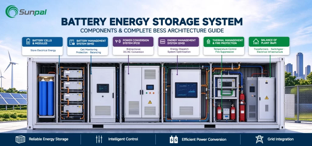
Battery energy storage systems have become the backbone of modern renewable power plants. As solar farms expand and grid operators demand greater flexibility, understanding every layer of a complete BESS architecture is essential for developers, EPCs, and asset owners. This guide breaks down battery energy storage system components from the plant level all the way to the individual cell, explaining how PCS, EMS, BMS, liquid-cooling systems, and safety features work together to deliver reliable, high-performance energy storage.
Whether you are designing a new solar-plus-storage project or evaluating an existing utility-scale installation, this complete BESS architecture overview will help you make informed decisions on system integration, container design, and long-term performance.
Why BESS Architecture Matters for Solar Energy Storage Projects
Solar generation is inherently variable. Pairing photovoltaic arrays with a well-engineered battery energy storage system turns intermittent solar power into dispatchable, firm capacity. The difference between a high-performing project and one that under-delivers often lies in how thoroughly the BESS components are integrated across five distinct layers: Plant → Container → Rack → Module → Cell.
At Sunpal we design and integrate complete systems with particular focus on containerized solutions, advanced PCS coordination, intelligent BMS and EMS platforms, and liquid-cooling thermal management. The following sections walk through each layer and the critical components that define modern BESS architecture.
Understanding Complete BESS Architecture and System Integration
A modern battery energy storage system is far more than a collection of batteries. It is a tightly coordinated power plant that must communicate with the grid, respond to market signals, protect itself under fault conditions, and maintain optimal temperature for decades of operation.
Successful BESS system integration requires every component—from the medium-voltage switchgear down to the thermal propagation barriers between cells—to function as part of a unified whole. Poor integration leads to reduced efficiency, accelerated degradation, or safety risks. Strong integration, by contrast, maximizes round-trip efficiency, extends cycle life, and simplifies operations and maintenance.
The five-layer model provides a clear framework:
- Plant level – grid interface and overall control
- Container level – the modular, transportable building block
- Rack level – electrical and thermal aggregation
- Module level – packaged groups of cells
- Cell level – the fundamental energy storage unit
BESS Integration: Performance Comparison
AC Round-Trip Efficiency
Cycle Life
Lifetime Energy Throughput
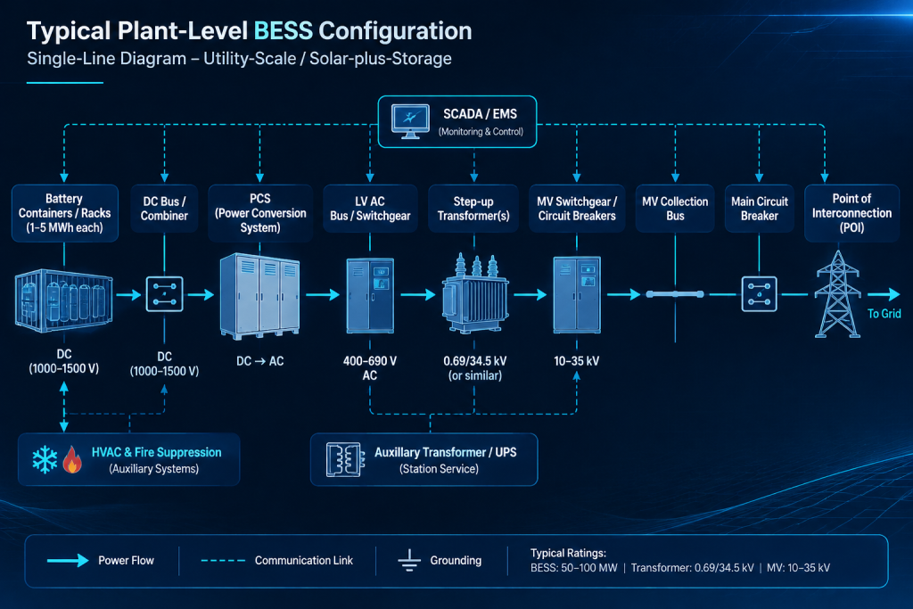
Plant Level: The Command Center of Utility-Scale BESS
At the plant level the battery energy storage system interfaces directly with the utility grid or the solar plant's point of interconnection. This layer determines how the entire facility behaves under normal and contingency conditions.
Power Conversion System (PCS)
The PCS is the bidirectional bridge between the DC battery side and the AC grid. Modern PCS units support both grid-following and grid-forming modes, enabling the BESS to provide synthetic inertia, black-start capability, and precise voltage and frequency control. In solar-plus-storage applications the PCS must also coordinate rapid charge and discharge cycles to capture midday solar surplus and discharge during evening peaks.
MV Switchgear and Transformer
Medium-voltage switchgear provides protection, isolation, and switching at the collection voltage (typically 10–35 kV). Step-up transformers raise the voltage to transmission levels when required. These components must be sized for the continuous and short-circuit ratings of the full plant and coordinated with the PCS protection settings.
SCADA and Energy Management System (EMS)
SCADA gathers real-time data from every container, PCS, and meter. The EMS sits above SCADA and makes the economic and operational decisions: when to charge from excess solar, when to discharge into the market, how to provide ancillary services, and how to respect state-of-charge and warranty constraints. An advanced EMS can increase project revenue by 10–20 % through optimized market participation while protecting battery life.
Container Level: The Workhorse of Modern BESS Design
Most utility-scale projects today rely on factory-built BESS containers. These standardized enclosures house the battery racks, local power distribution, thermal management, fire suppression, and communication equipment. Containerized design dramatically shortens on-site construction time and improves quality control.
A well-designed BESS container must satisfy structural, environmental, and safety requirements while maximizing energy density. Typical ratings range from 2 MWh to more than 5 MWh per 20- or 40-foot container, depending on cell chemistry and thermal strategy.
Liquid Cooling Versus Air Cooling
Thermal management is one of the most critical decisions at the container level. Air-cooled systems are simpler and lower in first cost, but liquid-cooling systems deliver superior temperature uniformity, higher power density, and longer calendar and cycle life—especially important for solar energy storage projects that experience daily deep cycling. Liquid-cooled containers can maintain cell temperatures within a narrow band even under high ambient conditions or rapid charge/discharge from large solar arrays.
Fire Suppression and Safety Systems
Each container incorporates multi-level detection (smoke, heat, gas) and active suppression, often using clean-agent or water-mist systems. These systems communicate directly with the BMS so that an event in one container can be isolated without shutting down the entire plant.
Air-Cooled vs. Liquid-Cooled BESS
Rack Level: Aggregating Power and Managing Heat
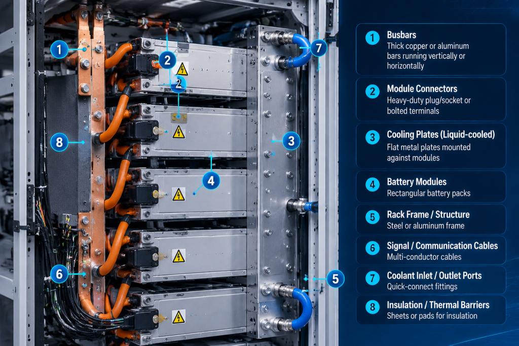
Inside each container, battery racks form the next structural and electrical layer. Racks typically contain multiple modules connected in series or parallel to achieve the desired DC voltage and capacity.
Heavy-duty busbars collect current from the modules with minimal resistance and heat generation. Proper busbar design is essential for efficiency and for safe maintenance access. Racks also incorporate the first stage of thermal interfaces and mechanical barriers that help contain any thermal event.
Sensors at the rack level feed voltage, current, and temperature data upward to the BMS, enabling precise control and early fault detection.
Module Level: The Practical Building Block
Battery modules group individual cells into manageable, replaceable units. Each module includes its own monitoring circuit board that measures cell voltages and temperatures and performs balancing. Modules are designed for straightforward installation into racks and for eventual replacement if needed during the project life.
Thermal interface materials and mechanical structures within the module play a key role in transferring heat to the container's liquid-cooling system and in limiting the spread of any cell-level anomaly.
Cell Level: Where Energy Storage Begins
At the foundation of every battery energy storage system are the individual cells. Whether lithium iron phosphate or other advanced chemistries, cell selection influences energy density, safety characteristics, cycle life, and cost. Consistent cell quality and tight manufacturing tolerances are prerequisites for predictable system performance over 20-plus years of solar energy storage duty cycles.
All higher-level controls and protections exist ultimately to keep each cell within its optimal voltage, current, and temperature window.
Cell-Level Performance Metrics
Cycle Life vs. Depth of Discharge
Temperature Sensitivity
Safety Systems That Protect the Entire Architecture
Safety is engineered into every layer. The Battery Management System (BMS) continuously monitors cell, module, and rack conditions, enforcing protective limits and communicating status to the EMS and SCADA. Thermal propagation barriers—special materials and design features between cells and modules—slow or stop the spread of heat in the rare event of a cell failure. Coordinated fire-suppression systems provide the final layer of defense.
When these systems are properly integrated, a modern BESS achieves the high safety standards required by utilities, insurers, and financing parties.
Real-World Example: 100 MW Solar-Plus-Storage Architecture
Consider a representative 100 MW / 400 MWh BESS paired with a large solar farm. The plant level includes multiple PCS units totaling more than 100 MW, MV switchgear, step-up transformers, and a central EMS that optimizes both solar generation and storage.
At the container level, dozens of liquid-cooled containers, each rated several megawatt-hours, are arranged in rows with shared balance-of-plant systems. Inside, racks and modules are monitored by distributed BMS units that report to the plant EMS. Thermal management maintains tight temperature control despite daily solar charging peaks, while fire-suppression and thermal barriers provide layered protection.
This configuration demonstrates how careful BESS system integration across all five layers delivers reliable capacity, high round-trip efficiency, and strong project economics.
Best Practices for BESS System Integration and Future Trends
Successful projects share several common practices: early involvement of the system integrator in design, rigorous factory acceptance testing of containers, clear communication protocols between PCS, BMS, and EMS, and selection of liquid-cooling technology for high-cycling solar applications.
Looking ahead, we see continued increases in energy density, wider adoption of grid-forming PCS, tighter real-time coordination between EMS and BMS, and greater use of digital twins for predictive maintenance. These advances will further improve the value of battery energy storage systems in solar-dominated grids.
Conclusion: Building Reliable Solar Energy Storage from the Ground Up
A complete understanding of battery energy storage system components—from the plant-level PCS, MV switchgear, transformer, SCADA, and EMS down through containers, racks, modules, cells, liquid-cooling systems, busbars, thermal propagation barriers, and fire suppression—is essential for delivering high-performing, bankable projects.
By approaching BESS architecture as an integrated five-layer system rather than a collection of separate parts, developers and owners can maximize efficiency, safety, and lifetime value. Sunpal's focus on container design, system integration, advanced PCS/BMS/EMS coordination, and liquid-cooling thermal management is aimed at helping the industry achieve exactly these outcomes.
For deeper technical details on individual subsystems or to discuss a specific solar-plus-storage application, explore our related resources or contact our engineering team.